
Summary: The new BRARA DMR Repeater and UHF Antenna were installed on Wednesday, July 31, and is operational for local communications on 442.875 MHz +5 MHz Offset (previous UHF repeater frequencies) with Color Code 1 (CC-1), Time Slot 2 (TS-2), Talk Group 311037. Connection to Brandmeister is still pending (non-operational).
Details: On Tuesday, June 30, the Motorola SLR5700 DMR Repeater was programmed by Jerry Zaza. The repeater is Brandmeister repeat number 311037 and the local talk group was programed to be 311037. He tested local communication between two handhelds on TS-2 TG-311037, tested the connection to Brandmeister with the Ethernet connection, made sure the repeater would work locally even without an Ethernet connection, and made sure the repeater was broadcasting an analog CW ID every 10 minutes. After testing, which required a low power setting, he set the power setting back to maximum. Robert Eng picked up the DMR repeater and the Ethernet Microwave Antenna from Jerry for installation the next day.
On Wednesday, July 31, at 9:00 AM, Art Lewis, Gerry Gawaldo, and Robert Eng met at the BRARA shack and picked up the new UHF 4-element folded dipole antenna and transported it to the repeater site.
On Wednesday, July 31, at 10:00 AM, the team of Art Lewis, Lewis Lehman, Gerry Gawaldo, Grant Baron, Pablo Solsona, and Robert Eng met at the repeater site at the One Park Place building at the northwest corner of Yamato Road and I-95. The following was performed:
1. The new UHF antenna, tools, and the Microwave antenna were lifted by rope to the roof (top level) of the building. They had to be roped up because it was impossible to bring them up the vertical ladder which leads up to the roof.
2. The old UHF repeater antenna was removed. The mounting nuts were relatively easy to remove (ie they were not frozen).
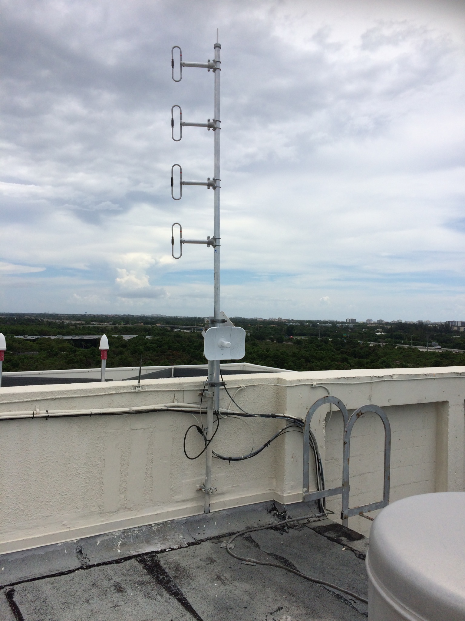
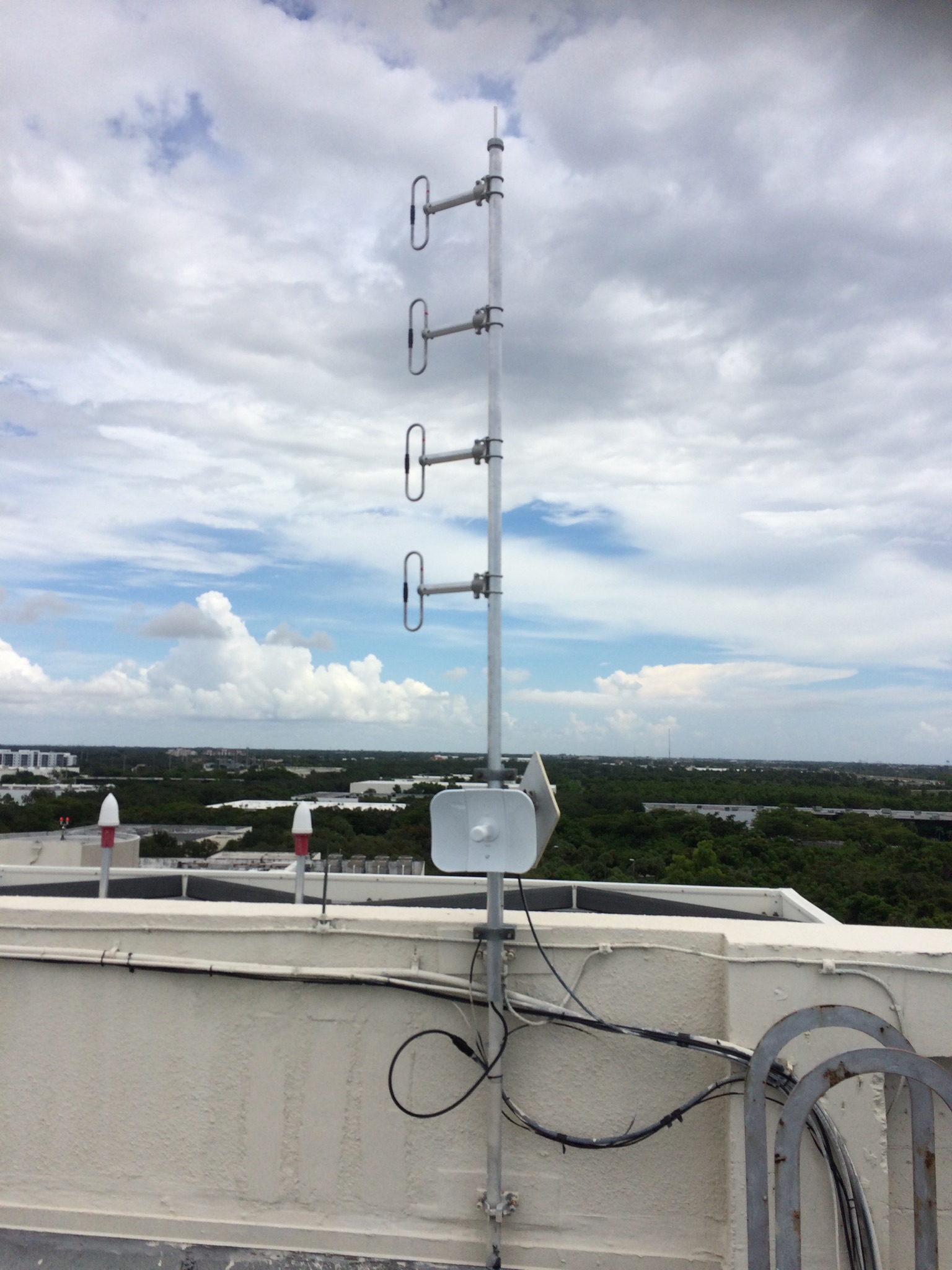
3. The new UHF antenna was installed in same place as the old antenna using the existing hardware. SWR of new antenna was checked with a Rig Expert AA-600 Antenna Analyzer. SWR was around 1.2. The new antenna was connected to the existing coax cable. The new antenna has a male N connector and the existing cable had a female N connector. Connection was sealed with black tape.
4. The existing Ethernet cable was identified and tested with an Ethernet Cable tester. All 4 pairs and the shield of the cable tested OK.
5. Internet Microwave Antenna was mounted on the bottom of the UHF antenna mask slightly above the edge of the wall around the roof. Ethernet cable was attached. Antenna was leveled and pointed towards FAU.
6. Old UHF antenna and tools were lowered from roof using rope.
7. DMR Repeater was installed in repeater rack. Repeater transmit and receiver ports were hooked to duplexer. The transmit port were both N connectors but the receiver port required a female N to male BNC adapter (repeater receiver port is a female BNC).
8. Ethernet cable from Microwave Antenna was hooked to POE power supply, then cabled to an Ethernet Switch. The LAN1 port of the repeater was also connected to the Ethernet Switch.
9. Repeater was powered on. Gerry Gawaldo had a DMR handheld programmed for CC-1, TS-2, Talk Groups (TG) , 91 (WW) , 93 (NA) , and 311037 (BRARA). Found that Talk Groups 91, 93, 311037 made the repeater respond (transmit LEDs on front panel of repeater lit) but TG-9 had no response. Do not test actual voice communication because we only had one DMR radio.
Sometime on Wednesday afternoon, it appeared the repeater stopped working. Robert Eng could not get his CS800D at home to handshake with the repeater (getting Call Failed message) and Gerry Gawaldo could not longer contact the repeater with the same radio he used when we tested the repeater after installation.
On Thursday, August 1, at 11:00 AM, Art Lewis, Lewis Lehman, and Robert Eng went back to the repeater site to check the DMR repeater. The red alarm LED was lit, and it obviously had shutdown. Added a right angle adapter to the top of the repeater rack to relieve strain on coax going to antenna. Measured transmit power of DMR repeater – was about 50 watts when keyed up. Measured SWR of antenna plus coax (where coax connects to duplexer) and SWR was 1.3. Tested communication between two DMR handhelds on TG 311037 both near the repeater and outside in parking lot and voice communication works OK.
The Internet connection portion at the repeater site should be complete (other than the antenna aiming may need to be refined). The FAU portion of the Internet connection still needs to be completed in order for the connection to Brandmeister to work.
If I forgot or misstated something, please feel free to correct me. As one gets older, the memory starts to fail.
A million thanks to everyone that helped with this effort to get the DMR repeater up and running. Greatly appreciate your time, effort, and expertise.
73
Robert Eng W1ENG